Focus on marine electronics

Taking stock of measuring instruments in 1980
In terms of navigation instruments, we differentiate between measurement devices – wind speed and direction, boat speed, distance traveled and depth – and those used for positioning and communication.
By 1980, the era of trailing logs and astronomical calculation tables is over. Recreational boaters have access to quite sophisticated resources. Manufacturers or importers offer electronic packages combining wind vanes, anemometers, logs, speedometers and depth sounders, with repeaters on deck.
For the anemometer, the sensor consists of three cups driving a generator or pulse counter. The information is filtered, particularly to eliminate the boat’s movements, then displayed on an indicator and possibly on the repeater. The displays vary depending on the supplier, ranging from digital to liquid crystal or analog, and could be combined with the wind vane, displayed numerically or on a circular dial. For clearer reading, some manufacturers provide two dials for more precision, one for close-hauled and the other for running.
Several systems were offered to measure the boat’s speed. A propeller or turbine spins a generator or creates pulses. There is also another method, without any rotation, using a sensor that inclines depending on the water pressure. After amplification, the current voltage or pulse number is related to a unit of time. The boat’s speed is then indicated with a galvanometer or displayed using diodes or liquid crystals.
Another method uses an electromagnetic sensor. This sensor generates an alternating magnetic field below the boat and measures the resulting electric field generated by the boat’s speed. The control box converts the sensor signal and sends the data to the display. Lastly, a new device uses the Doppler effect based on measuring a frequency shift between the emission and reception of moving ultrasounds.
The depth sounder is often the first electronic device on a boat. It makes it possible to navigate by monitoring a third dimension: depth. Its principle is simple: a transceiver emits ultrasounds into the water. The signal, traveling at 1,500 meters per second, is sent to the seabed and returns to the receiver. The travel time is simply measured to determine the depth. The transducer, placed on the bottom of the hull, is a piezoelectric capsule connected to the transceiver. In general, the measuring clock is an electric motor driving an arm with a neon bulb or diode. Many models have an alarm to warn if the boat approaches a shoal line or channel limit.
Some devices have a microprocessor or filter to correct or eliminate unwanted echoes. Depth recorders print depths up to 1,200 meters on paper and are three to five times more expensive. At the 1980 recreational boat show, the Salon de la Navigation de Plaisance, Grimaud Marine presents the first measurement system managed by a computer, the Hercules 190, from the American manufacturer Brookes & Gatehouse. Besides the 150-gram carbon fiber wind vane at the masthead, the sensors are connected to a computer that calculates performance at various speeds. Channels are provided to integrate the system with the compass and an autopilot. It can also monitor the batteries and engine oil pressure, or indicate the best RPM efficiency.
Positioning
The simplest way to determine your position on a sailboat is to plot your estimated positions on a chart based on your course, speed and drift. To check your location at the end of a crossing, or in fog, a radio direction-finding fix can correct the position. By orienting the antenna on the device toward at least two transmitters ashore, a radio beacon or radio marker, directions can be taken and plotted on your chart to determine the intersection point where you are located.
In 1980, radio direction-finding devices are already automatic, widely using microprocessors to store transmitter frequencies and data and perform calculations. They have an integrated compass and, in some cases, receive longwave, mediumwave and even marine SSB bands.
The Loran – Long Range Navigation – system uses sequenced signals, a series of eight or nine pulses of around 10 cycles, emitted by at least three stations. The receiver measures each signal’s arrival time to determine the boat’s position.
Each chain of transmitters, with its own cycle, has at least three stations: one master and two secondaries. The advantage with this system is that the waves are reflected off the ionosphere, supporting a very long range.
On our coasts, Loran is mainly used in the Mediterranean. There are around 67 stations in the northern hemisphere, with the tallest antennas reaching 411.48 meters. In France, there are two stations from 1985: in Soustons in the Landes and Lessay in Cotentin, with 213 meter pylons.
At the 1980 London Boat Show, the English firm Thomas Walker, known for its bronze propeller logs, highly sought after by maritime antique dealers, presents the Sat-Nav 810, the first accessible satellite navigator. It uses signals from six US Navy Transit satellites orbiting the poles at an altitude of 1,000km. For reception, it requires an approximate position within 60 miles. When a satellite is in view – 16 passes every 24 hours – the Transit receiver can calculate a boat’s position within 15 minutes, with a precision of around 200 meters.
In 1980, the radars available for recreational boats are still similar to those used for fishing and trade. This equipment is suitable for boats large enough to support significant electrical consumption and antennas weighing between 32 and 50 kilograms.
At the time, radar screens are circular, with scanning, and a range of 48 or 72 miles is significant compared with the actual needs involved.
Communications
Single Side Band (SSB) is a radio transmission mode operating in High Frequencies (HF) on decametric waves between 2 and 25 MHz. It makes it possible to communicate over very long distances between sailors, transmit distress messages, communicate and receive weather bulletins virtually worldwide. Its long range is due to the fact that the waves are reflected on the upper part of the atmosphere, the ionosphere. Sailors have to declare their equipment and hold an operator certificate. From January 1, 1982, coastal station transmissions use SSB, requiring all the old radio direction-finding receivers to be renewed or adapted.
For short-range communication, marine VHF radiotelephones are still quite heavy and expensive, but quickly improving. For instance, they can be equipped with keyboards, diode displays and, above all, synthesizers, grouping together 55 channels. The range of VHF waves is limited to around 25 miles, enough to communicate with a visible ship, helicopter or plane.
In the round-the-world races in the 1970s, crews reconstruct their weather maps from Morse code messages broadcast by stations on land. By 1980, large racing multihulls are equipped with the Nagrafax weather chart receiver. While the device itself is sophisticated, the principle is simple: transmitters worldwide broadcast maps that are analyzed line by line.
Each point’s brightness is converted into an electric signal. The information is inscribed on special paper, like old telephone faxes, producing a map.
In the 1980 La Baule-Dakar race, Marc Pajot on Elf Aquitaine veers east to find some wind, while Tabarly on Paul Ricard goes straight into a calm zone due to an electrical fault.
Evolution, revolution
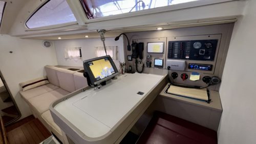
By the late 1990s, the navigation equipment on sailing models has integrated electronics. You can read your position on a computer screen with marine charts stored in its memory. Depth sounders, logs, radiotelephones, satellite navigators and radars become lighter, simpler to operate and cheaper. With navigation systems, microcomputers ramp up the performance levels offered and ensure remarkable reliability. Screens proliferate on all receivers, making them clearer to read. Electronics also appear in onboard electrical equipment, electric and hydraulic pilots, cooling and heating units, as well as naturally in managing the electrical circuits. In the late 1980s, the first color screens appear.
Since Sputnik’s launch in 1957, satellite telecommunications have seen extensive research and investment. The Transit system has been designed for the precise targeting of Polaris missiles on US nuclear submarines. The project, launched in 1958, becomes operational in 1966.

In 1988, the last Transit satellite is put into orbit, but the introduction of the first GPS (Global Positioning System) satellites by the US military makes it obsolete. Precision improves from 200 meters to less than 5 meters for civilian use.
The GPS system includes at least 24 satellites orbiting at an altitude of 20,200 kilometers. Spread over six orbits, they continuously transmit on two frequencies modulated by several time-stamped codes with atomic clocks and a navigation message. This message makes it possible to know their exact position at a given time. The GPS receiver captures signals from at least four satellites. By calculating the signal propagation time between the satellites and itself, it determines the distance separating them and can locate itself in three dimensions, revolutionizing the positioning concept.


